2015/09/30

AC 220V wireless system remote control shutter climb or descend

I want to buy a radio system for my 9 shutters (220 V), wireless control, 9 receivers and 1 Remote, climb or descend in all my components by one remote.
Answer:
We introduce the wireless remote control system to you according to your requirement. It is model: S1FM-AC220 CB-2The receiver’s (S1FM-AC220)working voltage is AC 100~240V. The transmitter (CB-2) is 2 channels and remote control distance is 1000m/3000ft theoretically. If you want to remote control shutter, you need to mount receiver to the motor of shutter. Then you can use the wireless transmitter to remote control shutter climb or descend by controlling motor rotates. Besides you can use one transmitter to remote control 9 receivers at the same time because of one transmitter can remote control several receivers simultaneously.

Here is the circuit diagram of receiver. Firstly you need to connect live wire to “L” terminal and neutral wire to “N” terminal. Secondly you can connect AC motor of shutter’s the top of slot to terminal “UP”, “COMMOM” and “DOWN” of receiver. Then supply power to receiver. When you press the button of transmitter, the motor will rotates and drives the winder of shutter. The shutter will climb or descend by wireless remote control.

This is the operation procedure of wireless remote control system:
When you press and hold big button of transmitter: Terminals UP and COMMOM directly output AC110V / AC220V; motor rotates continuously in positive direction; shutter climb.
Release button: Stop the motor.
When you press and hold small button of transmitter: Terminals DOWN and COMMOM directly output AC110V / AC220V; motor rotates continuously in reversal direction; shutter descend.
Release button: Stop the motor.
Finally you can also enter into our website and search the wireless remote control system as following:
The transmitter CB-2:
The kit of S1FM-AC220 & CB-2:
Online shop:

2015/09/28

Reversing Single Phase Capacitor Start Motor By Remote Controller

One customer said he had a 220V single phase capacitor start motor; it rotated in one direction (seen from the first picture below). And he’d like to change it to rotate in forward and reversal direction using our motor remote controller.
According to this picture, we learn that it can also rotate in another direction by changing wiring position of Red line and Yellow line.
We suggest him use motor remote controller model of 0020318 (S1FC-AC220 & CV-4).Picture on the following shows how to wire the motor and capacitor to the receiver. So that the motor can be remote controlled in forward and reversal direction.
Our shop online: www.ourautomation.com

2015/09/18

How to Wire Linear Actuator Control for Skylight Window?

Do you know how to wire a linear actuator control to skylight window, so that the skylight window with the linear actuator control can be remotely controlled from anywhere within the reliable distance?
Let’s have a try.
Firstly, we need to prepare these things:
1 x 12V remote control switch for motor (transmitter & receiver)
2 x 12V linear actuator motors
1 x DC 12V power adapter
*Maximum current of the remote controller is up to 10amp which is enough for controlling two linear actuator motors.
Secondly, wire two linear actuator controls to the receiver according to the wiring diagram.
Finally, control the linear actuator motor by the remote transmitter.
Press button ▲: motor rotates in forward direction, the skylight window is open.
Press button ▼: motor rotates in backward direction, the skylight window is closed.
Press button ■: rotation stops.

2015/09/16

Long range RC

 Long range RC for the track can easily be done by our new products
    This is a real case for the long range RC.
    Someone needs to set up long range RC light for the track and this would be done with wireless switching. Our new long range RC products can help him to achieve this operation.
    He said that the signal needs to travel at least 3000 meters so the 5000m setup would be best. The wireless receivers will trigger emergency flashing beacons.The layout is for motorcycle oval track competition and the remote controller and wireless receivers for the long range RC need to be operated by officials to ensure the safety of all competitors. This long range RC is done by operating warning revolving beacons. For this reason the customer need our best operating combinations over a distance of probably 4000 to 4500 meters with direct line of sight available to remote control light switch….so he gather the 5000m Long Distance combination (with separate antenna) would be the best option for the remote light switch.
12 volt equipment is being used for all emergency lighting via a 12 Volt DC power source.
filename-1
MP1,MP2,MP3 and MP4 are corner marshalling points and long range RC only need the ability to switch the corresponding relay for that corner (MP1 to L1, MP2 to L2, MP3 to L3 and MP4 to L4 yellow on diagram). There needs to be no interference between each of these MP points so they can be operated independently of each other. Therefore each MP remote controller only needs to be one (1) channel. 
The RF remote controller CC1 for the long range RC light -Is the main central control for the marshalling and is operated by the steward of the event. The Steward will be mobile so this remote controller will not be at any fixed point. To enable the Steward to have total control and over-ride the operations of officials at all MP points this remote controller for the remote light switch will need to be of 6 Channel operation, one channel for each MP (yellow) point (channels 1 to 4) and one channel (number 5) to operate simultaneously all RED receivers on points L1, L2, L3 and L4. This is to enable the stoppage of a race at any time by switching to a “STOP” light at all these points. Button number 6 can be spare.
SG1 – Is for the operation of the starting mechanism for each race (which could be up to 100) during the event.
This long range RC for the remote light switch needs to be 2 Channel to enable the switching of 2 GREEN (GL1 and GL2) lights at the starting area from Channel 1 and Channel 2 will activate 2 solenoids (SR1 and SR2). Therefore the long range RC for the remote light switch needs to be 2 channel and SR1, SR2, GL1 and GL2 receivers all each need to be 1 channel. GL1 and GL2 have to operate simultaneously from Channel 1 and SR1 and SR2 have to work simultaneously from Channel 2.
    According to all the information he has mentioned above, we recommend him a series of long distance wireless remote control kits to long range RC light switch. The theoretical working distance of the long range RC can reach about 5000m.
2345_image_file_copy_6
These long range RC kits have feedback function and two ways working mode.
With the feedback function, they can let the user know whether he/she had already connected the remote controller and wireless receiver for the remote light switch successfully in such a long distance.
Two ways working mode: When the wireless receiver for the long range RC gets the signal of remote controller, it will immediately send a return signal to the remote controller. When the remote controller  receives the feedback signal of the wireless receiver for the remotte light switch, the remote controller for the long range RC will exude a buzzing sound like “D~” which means it receive the feedback signal successfully.
The wireless receiver for the long range RC is waterproof case with waterproof connectors. The wireless receiver for the remote light switch can be installed outdoors. They are also high power remote light switch control kits, each relay output can work at maximum current 30A.
External magnetic sucker antenna with 5meters cable, the antenna for the remote light switch can be installed outside the building to get better working distance
The long range RC kits can be used to remote light switch, agriculture automation, industry automation, and home automation. It can control products on land, water and air, especially in a long distance, such as business signs, motorboat, farm, pasture, offshore unmanned operation, field call, remote security alarm, unmanned aerial vehicle, etc.

2015/09/15

How to Remote Control Electric Wolf Whistle Car Horn

Question from customer:
“I have a classic car with a 12 volt electric wolf whistle. I’d like to trip the wolf whistle from outside the car during cruise nights. How would I accomplish this?”
wolf whistle car horn
Answer:
We recommend the model of 6000ft 6V/9V/12V/24V power output remote control kit (S1X-DC06/09/12/24-ANT2 & CB-2). Usually, 12 volt is default voltage for this kit. If you input 12 volt power to that receiver, receiver will output 12 volt for your wolf whistle horn. It is easy to practice with using of rf remote control because rf signal has advantage of passing through doors, walls, trees as well as other obstacles and long distance transmitting. We add external extended antenna to extend the range of the remote controller and make its transmission distance reach 6000ft/2000m in the open field.
1_01_1
Wiring is very simple. You can wire your wolf whistle horn to output terminals of receiver directly.
The outputs from the receiver can drive relay connected to your wolf whistle horn. Your device will work.
circuit
Usage:
Setting different control modes (We have set the receiver as Toggle mode before delivery. If you want to use other modes, do as following):
1) Setting control mode Toggle: Only connect Jumper-2.
Press big button: Turn on the relay, terminal A&B output DC power.
Press big button again: Turn off the relay, terminal A&B no output.
2) Setting control mode Momentary: Only connect Jumper-1.
Press and hold big button: Turn on the relay, terminal A&B output DC power.
Release big button: Turn off the relay, terminal A&B no output.
3) Setting control mode Latched: Do not connect Jumper-1 and Jumper-2.
Press big button: Turn on the relay, terminal A&B output DC power.
Press small button: Turn off the relay, terminal A&B no output.
General speaking, you can set Momentary mode for wolf whistle horn. When you press a momentary button, your wolf whistle horn stays on as long as you maintain pressure on the button. When you stop maintaining pressure on the button, your wolf whistle horn stops sounding.

How to Trigger a Transmitter by current without Pressing Button

Question from customer:
I would like to use a 12v DC electric current to tell a remote to send a signal to the receiver. Do you have any remote transmitters that accept a current instead of requiring a button to be pressed?
Answer:
We recommend the DC 5~28V triggered transmitter (CB-2V). With external input wires, your dc12V electric current can be input transmitter CB-2V. Transmitter can be triggered at once and transmits an rf signal “ON”. When stop inputting DC power, the transmitter is triggered and then transmits an rf signal “OFF”. So this remote control transmitter can accept a current instead of requiring a button to be pressed. Its transmission distance is about 1000m/3000ft theoretically.
low current triggered transmitter
You can add a rocker switch between transmitter and its power supply. (the following picture shows)
current triggered
And you can make this transmitter work with a receiver. (Just like picture shown). When transmitter transmits “ON” signal, the lamp is on; When transmitter transmits “OFF” signal, the lamp is off.
control led lamp

How to Change an Ordinary Socket to a Remote Control Socket

Wireless Remote Control for Remote Control Socket

Remote control socket is a socket whose power switch can be controlled by a transmitter. This remote control socket may be any of a socket in your home. If you want a AC remote control socket, you may choose a wireless remote control kit.
With such combination, you can easily control receiver’s power switch with a transmitter. Applications include lights, motors, Doors, Locks, windows, blinds, cars and various equipments。
Model 0020136 (S1PXW-AC220-ANT2 & CC-2) is a wireless remote control kit that can be used for remote control socket. The receiver model 0020134 (S1PXW-AC220-ANT2) has one channel. Both its power input and power output are AC100 ~240V and the two are consistent, that is, when the power supply inputs AC100V power, the Terminal A and Terminal B will output AC100 V power. The transmitter 0021061 (CC-2) has 2 buttons and a sliding cover which can protect the button when you slide the cover up.
The working distance of this remote control socket can reach 5000 meters in an open ground.
Here is an application that you can use this kind of kit to control a AC remote control socket:
One of our customers wants to use a wireless remote control kit to control a AC remote control socket. The kit should have the following function: When press button 1 of the transmitter, the remote control socket’s power turns on. When press button 2 of the transmitter, the remote control socket’s power turns off. Then we will recommend him Model 0020136 (S1PXW-AC220-ANT2 & CC-2).
First of all, let’s see material preparation.
1 x 1 channel remote control receiver (S1PXW-AC220-ANT2)
2 x 2-button remote transmitter(CC-2)
1 x power plug
1x socket
1xlamp
1 x power supply
Some lines
2345_image_file_copy_8_2345看图王
Secondly, live wire and neutral live from the plug should be respectively connected to the power supply terminal “L” and “N” of the receiver, and live wire and neutral live from the socket should be respectively connected to the output terminal “+” and “-” of the receiver.
2345_image_file_copy_9_2345看图王
Thirdly, insert the plug into the power supply, switch on the socket’s power and insert the plug of lamp into the socket.
Operation:
Press button 1, relay begins, the socket’s power switches on and the lamp that has connected the socket is on;
2345_image_file_copy_10_2345看图王
Press button 1, relay begins, the socket’s power switches on and the lamp that has connected the socket is on;

 2345_image_file_copy_11_2345看图王

How to control 2 rolling shutters of motor remote control by one remote?

How to control 2 rolling shutters by one remote? – Our Automation
“How to remote control 2 rolling shutters open or close at the same time without going from here to there? The electric remote control motor of rolling shutters operate on 240V. Can you suggest something as a solution? Thanks.” One customer asked.
rolling_shutter.jpg
We suggested him choose two motor remote control  receivers model of S1FC-AC220 (operating voltage range is AC 100V ~ 240V); and one long distance remote transmitter CV-4.
remote_transmitter_and_receiver.jpg
As seen in the picture of remote, button ▲ is supposed to control motor of rolling shutters forward direction; button ▼ is to control reversal direction. Button ■ is to stop the rotation.
Wiring diagram is as follow:
Connect live wire to terminal “L” and neutral wire to terminal “N”. Then connect three wires of rolling shutter motor to terminals “UP”, “COMMON” and “DOWN”.
receiver-wiring-diagram.jpg
Press button ▲, 4 motors remote control of rolling shutter rotate continuously in forward direction at the same time.
Press button ■, rotation stops.
Press button ▼, 4 motors remote control of rolling shutter rotate continuously in reversal direction at the same time.
Press button ■, rotation stops.
Motor remote controll products can be found on www.ourautomation.com.

Rallycross Pneumatic Timer Switch

I attended a East Tennessee Region Rallycross earlier this year.  They were using a pneumatic timing switch instead of a stopwatch.  It seemed to be working very well.  The Middle Georgia Region where I live just started a Rallycross program but had been using stopwatches for timing.  The pneumatic switch is a much easier method than the stopwatch.
So, I contacted Ted Visscher who had built the system East Tennessee Region uses.  He shared some links to information for building the switches.  This link http://www.sccabb.com/forum_posts.asp?TID=9223 was a good start.  It led me to this link http://detroit-scca.org/e107/request.php?605.  The Detroit Region had designed a pneumatic switch and posted how they built it.  This was the switch setup I was looking for.
I started looking for the parts on the internet and found the suppliers listed below in the parts list below.  I posted the prices I paid for the parts as a reference.  They may be available cheaper by other vendors.
Pneumatic Timing System Parts List
  
 QTY    SIZE                                SPECIFICATION           COST                    SOURCE
2        #32NO-WB                     Switch                              $56.72            Kleen-Rite Corp.
2        1/2″                                  Wire Clamp                       $1.00            Ace Hardware
4        2 Contact Connectors       Hopkins 47965                    $5.98            Autozone
60′     3/8″IDx5/8″OD                  Rubber Hose                     $52.34            Kleen-Rite Corp.
4        3/8″                                 Hose Plug                           Free             Fabricated
4        1/4″x2″                             Eyebolt                                $3.16           Ace Hardware
10      5/8″                                 Hose Clamps                       $4.50           E-Bay
2        3/8″                                 Brass pneumatic “T”             $13.98          Ace Hardware
4        8″-10″                              Tent Stakes 86565                $3.89          Ace Hardware
4        21″                                  Rubber Bungees                   $3.52          E-Bay
2        35 Qt.                            Sterilite Latch Tote               $18.00          Family Dollar
2        RJ45                              Computer Connector              Free           Donated
250′   Cat-5                             Computer Cable                    Free           Donated
$160.09        Total
Then I looked up the Axware forum online at http://www.axwaresystems.com/forum/viewtopic.php?f=4&t=795 .  I learned from it that the Axware System hardware requires a normally closed circuit for the trigger.  So, the pneumatic switch needed a circuit to convert the normally open contacts to a normally closed signal for the Axware box.
They had a circuit they had designed using a Mosfet as a switch to convert from a normally open to a normally closed switch signal at http://www.raceamerica.com/download/techsup/antmr001.pdf.  It looked simple, so I built one for each switch inside a plastic electrical outlet box.
I hardwired some Cat-5 cable into the box to plug into the Axware System box with RJ45 connectors.  The circuit is powered by a 12v AC/DC wall wart that I hardwired to the circuit. The pneumatic switches connect to the box using a cable made as shown on the Axware drawing at  http://www.raceamerica.com/download/techsup/ancbl002.pdf .
Below is a listing of the parts I bought to make the normally closed circuits.
Normally Closed Circuit for Axware Box
QTY     SIZE                               SPECIFICATION           COST                    SOURCE
2        IRF-510                            Mosfet 276-2072                 $4.98         Radio Shack
2        10K Ohm                         1/4W Resistors 271-1335        $1.49           Radio Shack
1         120V/12V                          AC-DC 55057391              $11.99           Radio Shack
1         Single Outlet box             Plastic                              $0.59           Ace Hardware
2         RJ45                                Computer plugs               Free            Donated
1         Outlet box cover              with 2 RJ45 sockets            Free            Donated
4 ft.    Cat-5                               Cable                               Free            Donated
$19.05          Total
We tested the system at a Middle Georgia Region Rallycross on 03/15/2014.  It worked well, but we were getting some false tripping and the Axware system would loose track if we launched more than one car at the time.  We started using a stopwatch as a backup to the system to avoid too many reruns.
I am working on some ideas that may fix those issues.  I plan to try adjusting the sensitivity of the switch which may reduce the false triggers.  I also plan to put some baby powder in the air line to keep it from sticking together inside.
One thing we tried by the end of the day was to lessen the tension on the air line.  This allowed the diameter of the line to say larger which seemed to help during the fun runs.
With some adjustments, we should end up with a system that is very reliable.
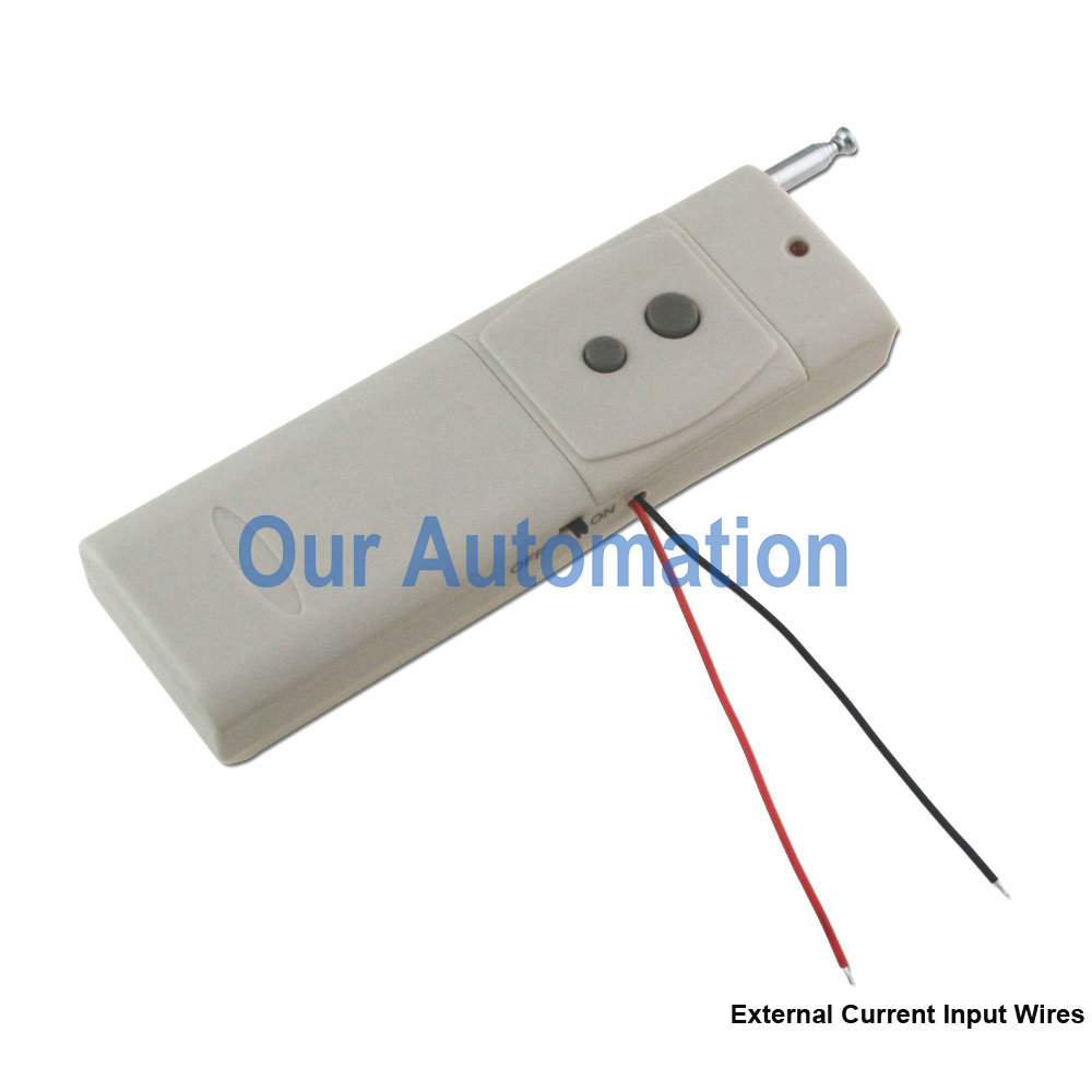
I am working an improvement which will make the system much easier to use and set up.  I found some wireless switches online at http://www.rfcontrolsystem.com/ .  They offer a two channel receiver with a transmitter.  The combo can be ordered with a short or long range capability and with an extra transmitter.  Each transmitter can be set to operate a separate relay inside the receiver.  The relays have normally open and normally closed contacts.  So, I ordered the parts below and began construction once they arrived.  It took about three weeks to get here from China.
Radios & Delay/Latch Circuit
QTY    SIZE                               SPECIFICATION           COST                    SOURCE
2        IRF-510                           Mosfet 276-2072                $4.98         ourautomation.com
1         2CH 2000M                    Transmitter & Receiver    $50.00       ourautomation.com
Kit  0020213
(S2U-DC06/09/12/24-ANT2 & CB-2)
1         2CH 2000M                    Transmitter                      $37.00      ourautomation.com
0021045 (CB-2N)
(This Transmitter would also work and is cheaper at $22.00   0021024 (CB-2))
1         120V/12V                         AC-DC Adapter                 $8.00       ourautomation.com
0010124 (A-02)
Insurance and Shipping       $18.99       ourautomation.com
2        IRF-510                           Mosfet 276-2072                  $4.98        Radio Shack
2        220uf 35V                       Capacitor 272-1029             $2.98        Radio Shack
2        10K                                Multi-turn Pot 271-0343        $5.98        Radio Shack
2        9V                                  Battery Clip 270-0324         $2.99        Radio Shack
$135.90        Total
I ordered one transmitter with leads already coming out of the transmitter to see if it could be attached to directly to the pneumatic switch.  It did work, but not well.  The transmitter was programmed to trigger once a second for four seconds to ensure that when the wires were connected through a switch that the signal was received by the transmitter.  That would cause issues for the Axware box.
I decided to attach the switch directly to the circuit board in parallel to the push-button switch to see if that would work.  It also worked, but again not well.  If the pneumatic switch was not held closed for about a half second, the receiver would not trigger the relays.  So, I needed a way to keep the signal from the pneumatic switch closed longer to ensure the receiver would trigger the relays.
I found a circuit at http://easy-electronics4u.blogspot.com/2012/02/simple-dc-timer-using-mosfet-onoff.html  that allows a delay to be used with another Mosfet circuit.  I used the equations they provided to calculate a circuit that can be kept closed for about .5 seconds to 3.5 seconds and is adjustable.
That is why there are several parts from Radio Shack in the list above.
Here is how the transmitters were rewired and the latching circuit added to the system.
The battery springs were removed by bending the tab back and forth until they snapped off. One of the two push button switches were shorted using a jumper soldered directly to the circuit board.
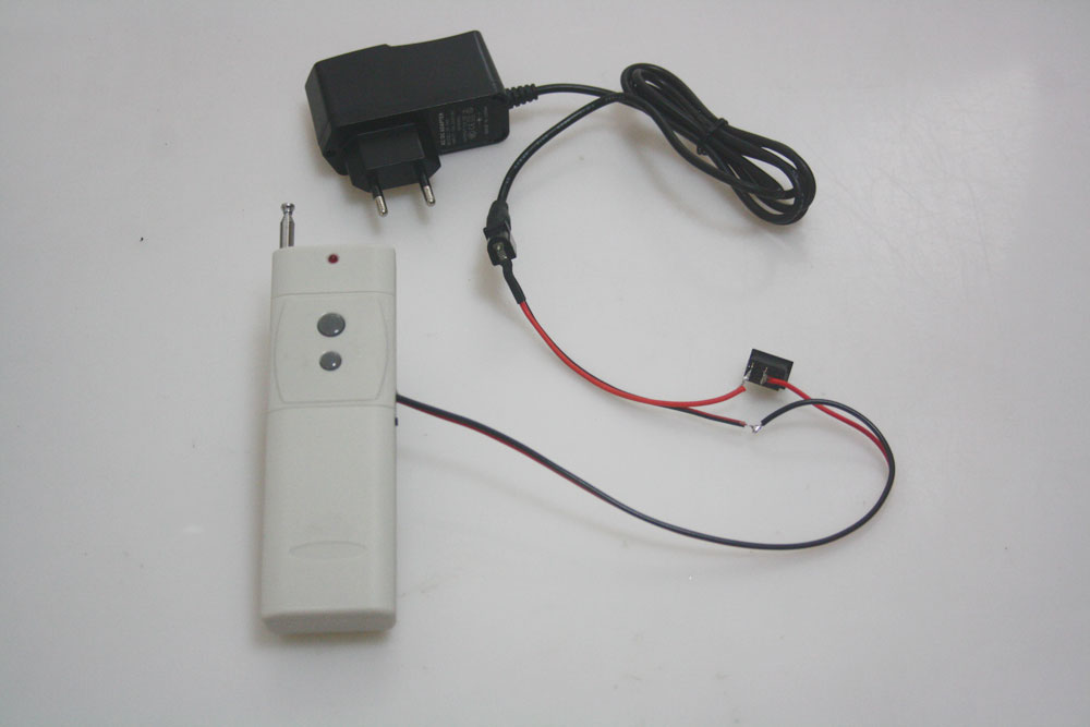
I found two old car chargers and cut the cords for use to attach the transmitters to the pneumatic switches.  These attach directly to the transmitters at one end and to a two prong plug at the other that matches the plugs on the switches.
I built the circuits by soldering the legs of the capacitor and trim pot. as shown.  Then I attached wires as shown and soldered the legs of the Mosfet into the circuit.  Leaving the circuit are three wires.  There is a B+, Ground and switched lead.  The cardboard is to separate my added parts from the circuit board.
The switched lead is attached to the ground terminal on the transmitter.  B+ from the battery is attached to the B+ terminal on the transmitter.  Then a lead is soldered onto the on/off switch and run to the latch circuit B+ lead.  This allows the transmitter battery to be turned off to save the batteries.
The 9V battery clips attach to the battery since the springs for the battery connections were removed.  Note the batteries will not fit back into the transmitter, so they were just taped on so the batteries can be replaced as needed.
The circuit triggers the receiver every time I tried it.  The latch holds closed for about a second so I did not even adjust it.  Funtional testing will have to wait until I can borrow the timer and laptop after the next autocross.
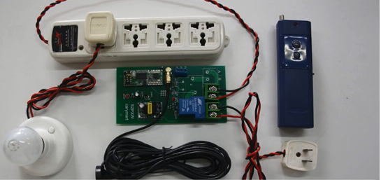
We got to test the timer using the radios on Saturday 04/05/2014.  It worked during testing but we did have a few issues.  While the transmitters were close to the receiver, it worked every time.  However, when we moved about 100 yards away, the receiver did not work every time.  Since there were trees and other obstructions we decided it worked well enough to test it at the next Rallycross on 04/26/2014.
Before then, I will find a small metal plate to attach the receiver antenna’s magnetic base to keep it standing vertically.  That may help since the receiver antenna was mounted horizontal on the table leg during our first test.  I may also use a piece of PVC pipe to set the transmitters in so their antennas will stay vertical.  The radios are supposed to be good for 300 meters.
The latch circuits seemed to do the job and the receiver was working well when we had signal.  The Axware Timer also seemed to accept the inputs without issue.
More to come after the next Rallycross.